Showing posts with label Rc Dictionary. Show all posts

Friday, August 30, 2013

Flutter: A phenomenon whereby the elevator or aileron control surface begins to oscillate violently in flight. This can sometimes cause the surface to break away from the aircraft and cause a crash. There are many reasons for this, but the most common are excessive hinge gap or excessive "slop" in the pushrod connections and control horns. If you ever hear a low-pitched buzzing sound, reduce throttle and land immediately.
Flutter (Aircraft Flutter)

Posted on Friday, August 30, 2013 by Rc Pilot

No comments

Friday, August 23, 2013

Field Charger: A fast battery charger designed to work from a 12-volt power source, such as a car battery.
Field Charger


Posted on Friday, August 23, 2013 by Rc Pilot

No comments

Thursday, August 8, 2013

Flare, the point during the landing approach in which the pilot gives an increased amount of up elevator to smooth the touchdown of the airplane.


Posted on Thursday, August 08, 2013 by Rc Pilot

No comments

Wednesday, August 7, 2013

Hinged control surface located at the trailing edge of the wing inboard of the ailerons. The flaps are lowered to produce more aerodynamic lift from the wing, allowing a slower takeoff and landing speed. Flaps are often found on scale models, but usually not on basic trainers.
Flaps


Posted on Wednesday, August 07, 2013 by Rc Pilot

No comments

Tuesday, August 6, 2013

Expanded Scale Voltmeter (ESV) : Device used to read the battery voltage of the on-board battery pack or transmitter battery pack.
Expanded Scale Voltmeter (ESV)

Posted on Tuesday, August 06, 2013 by Rc Pilot

No comments

Epoxy : A two-part resin/hardener glue that is extremely strong. It is generally available in 6 and 30-minute formulas. Used for critical points in the aircraft where high strength is necessary.

Epoxy Glue
Wikipedia Epoxy:
Epoxy is both the basic component and the cured end product of epoxy resins, as well as a colloquial name for the epoxide functional group. Epoxy resins, also known as polyepoxides are a class of reactive prepolymers and polymers which contain epoxide groups. Epoxy resins may be reacted (cross-linked) either with themselves through catalytic homopolymerisation, or with a wide range of co-reactants including polyfunctional amines, acids (and acid anhydrides), phenols, alcohols, and thiols. These co-reactants are often referred to as hardeners or curatives, and the cross-linking reaction is commonly referred to as curing. Reaction of polyepoxides with themselves or with polyfunctional hardeners forms a thermosetting polymer, often with strong mechanical properties as well as high temperature and chemical resistance. Epoxy has a wide range of applications, including metal coatings, use in electronics / electrical components, high tension electrical insulators, fiber-reinforced plastic materials, and structural adhesives. Epoxy resin is employed to bind gutta percha in some root canal procedures.

Posted on Tuesday, August 06, 2013 by Rc Pilot

1 comment

Monday, August 5, 2013

Endpoint Adjustment : This radio feature adjusts the length of servo travel in one direction (a single channel will have adjustments for two endpoints). If your plane rolls faster one way than the other, endpoint adjustments can correct the problem.
Endpoint Adjustment Servo
Endpoint Adjustment Schema

Servo

Posted on Monday, August 05, 2013 by Rc Pilot

No comments

Sunday, August 4, 2013

Elevator: Hinged control surface located at the trailing edge of the horizontal stabilizer, which provides control of the airplane about the pitch axis and causes the airplane to climb or dive. The correct direction of control is to pull the transmitter elevator control stick back, toward the bottom of the transmitter, to move the elevator upward, which causes the airplane to climb, and vice versa to dive.
Elevator Aircraft
Airplane, Propeller, Aileron, Rudder, Elevator

Posted on Sunday, August 04, 2013 by Rc Pilot

No comments

Saturday, August 3, 2013

Electronic Speed Control (ESC): Electronic speed controls replace the mechanical speed control and servo providing enhanced power efficiency and precision in an electric R/C car, airplane, helicopter or boat. In addition, they are lighter which improves the performance of some electric models.

esc single schematic
Wikipedia:
An electronic speed control or ESC is an electronic circuit with the purpose to vary an electric motor's speed, its direction and possibly also to act as a dynamic brake. ESCs are often used on electrically powered radio controlled models, with the variety most often used for brushless motors essentially providing an electronically-generated three phase electric power low voltage source of energy for the motor.

An ESC can be a stand-alone unit which plugs into the receiver's throttle control channel or incorporated into the receiver itself, as is the case in most toy-grade R/C vehicles. Some R/C manufacturers that install proprietary hobby-grade electronics in their entry-level vehicles, vessels or aircraft use onboard electronics that combine the two on a single circuit board.

Cars
ESCs designed for sport use in cars generally have reversing capability; newer sport controls can have the reversing ability overridden so that it can not be used in a race. Controls designed specifically for racing and even some sport controls have the added advantage of dynamic braking capability. The ESC forces the motor to act as a generator by placing an electrical load across the armature. This in turn makes the armature harder to turn, thus slowing or stopping the model. Some controllers add the benefit of regenerative braking.

Helicopters 
ESCs designed for radio-control helicopters do not require a braking feature (since the one way bearing would render it useless anyhow) nor do they require reverse direction (although it can be helpful since the motor wires can often be difficult to access and change once installed). Many high-end helicopter ESCs provide a "Governor mode" which fixes the motor RPM to a set speed, greatly aiding CCPM-based flight.

Airplanes 
ESCs designed for radio-control airplanes usually contain a few safety features. If the power coming from the battery is insufficient to continue running the electric motor the ESC will reduce or cut off power to the motor while allowing continued use of ailerons, rudder and elevator function. This allows the pilot to retain control of the airplane to glide or fly on low power to safety.

Boats
ESCs designed for boats are by necessity waterproof. Also, many are water-cooled. Like cars, boats need braking and reverse capability.


Posted on Saturday, August 03, 2013 by Rc Pilot

No comments

Thursday, July 25, 2013

Four Stroke (Four Cycle): Although a 4-stroke engine has less power than a 2-stroke engine of comparable size, there are advantages to 4-stroke engines. They do not require a muffler and are often quieter than most 2- strokes are with a muffler. They can swing a bigger prop than the same size 2- stroke engine. This is an asset in the large, slow-flying aerobatic and scale models where 4- stroke engines are usually mounted. Lastly, the fuel economy is better.

Posted on Thursday, July 25, 2013 by Rc Pilot

No comments

Flight Box: A special box used to hold and transport all equipment used at the flying field.
Flight Box
Flight Box

Flight Box Flight Box

Posted on Thursday, July 25, 2013 by Rc Pilot

No comments

Thursday, July 11, 2013

FHSS (Frequency Hopping Spread Spectrum) : 

 — A 2.4GHz radio system which switches from one "free" frequency to another every few milliseconds. While jumping from one to the other frequency, you are not spending much time on that frequency and this keeps out interference. See also: DSSS.
FHSS - (Frequency Hopping Spread Spectrum)

Wikipedia:
Frequency-hopping spread spectrum (FHSS) is a method of transmitting radio signals by rapidly switching a carrier among many frequency channels, using a pseudorandom sequence known to both transmitter and receiver. It is utilized as a multiple access method in the frequency-hopping code division multiple access (FH-CDMA) scheme.

Posted on Thursday, July 11, 2013 by Rc Pilot

No comments

DSSS

A 2.4GHz radio system which selects one (or two) of the available "free" frequencies and transmits only on the one(s) chosen. Like FHSS (Frequency Hopping Spread Spectrum) systems, it is resistant to electrical noise. See also: FHSS.
Direct Sequence Spread Spectrum

Wikipedia: In telecommunications, direct-sequence spread spectrum (DSSS) is a modulation technique. As with other spread spectrum technologies, the transmitted signal takes up more bandwidth than the information signal that modulates the carrier or broadcast frequency. The name 'spread spectrum' comes from the fact that the carrier signals occur over the full bandwidth (spectrum) of a device's transmitting frequency. Certain IEEE 802.11 standards use DSSS signaling.


DSSS - Direct Sequence Spread Spectrum
Direct Sequence Spread Spectrum (DSSS) is a spread spectrum technique whereby the original data signal is multiplied with a pseudo random noise spreading code. This spreading code has a higher chip rate (this the bitrate of the code), which results in a wideband time continiuous scrambled signal.

Direct Sequence Spread Spectrum
DSSS significantly improves protection against interfering (or jamming) signals, especially narrowband and makes the signal less noticeable. It also provides security of transmission if the code is not known to the public. These reasons make DSSS very popular by the military. In fact, DSSS was first used in the 1940s by the military.

DSSS can also be used as a multiple access technique, whereby several different pseudo random spreading codes are being used simultaneously. This multiple access technique is better known as Direct Sequence CDMA.
DSSS is e.g. used in IEEE 802.11b and Zigbee.

Posted on Thursday, July 11, 2013 by Admin OG

No comments

Electric Starter:

A hand-held electric motor used for starting a model airplane engine. Usually powered by a 12-volt battery.

Posted on Thursday, July 11, 2013 by Rc Pilot

No comments

Friday, July 5, 2013

Electric vs. Gas Cars: Electric vehicles are the most popular choice in R/C car racing. They are quick, quiet, easy to build and comfortable for the beginning R/Cer to drive. The electric cars are powered with a rechargeable nicd battery that can be charged in as little as 15-20 minutes. A vehicle with a stock motor will provide about 6-8 minutes of run time; with a couple of batteries and a 15 minute charger, an electric car or truck is ready for hours of use. The popularity of Gas vehicles has increased tremendously over the last few years. The explosive power and acceleration of a gas powered car or truck is exciting to watch. Gas vehicles are powered by a small two-cycle engine burning glow fuel (not gasoline!), and many modelers enjoy the realistic sound and smell that goes along with gas powered racing. Some gas models can reach speeds over 50mph! The wider availability of pull-start engines and the new wave of 1/10 scale vehicles has made it much more affordable for the beginner to enter gas-powered racing.
Electric vs. Gas Cars

Posted on Friday, July 05, 2013 by Rc Pilot

No comments

Thursday, July 4, 2013

Down Thrust: Downward angle of the engine relative to the centerline of the airplane. Down thrust helps overcome the normal climbing tendency of flat bottom wings.
Down Thrust


Posted on Thursday, July 04, 2013 by Rc Pilot

No comments

Wednesday, July 3, 2013

Minor dent or damage to the structure. Also, a nick in a prop. Dinged props must be replaced.

Posted on Wednesday, July 03, 2013 by Rc Pilot

No comments

This radio feature permits you to check servo operation without broadcasting a radio signal. A cable connects the transmitter to the receiver. Direct servo control is very useful for on-the-ground control checks.
DSC - Direct Servo Control

Futaba Description:
Direct Servo Control (DSC): High-end convenience feature which allows control/adjustment of servo function without sending signal through receiver. Requires optional DSC cord (FUTM4250) and DSC-compatible receiver such as R149DP and R113IP.

Posted on Wednesday, July 03, 2013 by Rc Pilot

No comments

Friday, June 14, 2013

Dihedral
Image: Dihedral

Dihedral:

The V-shaped bend in the wing. Typically, more dihedral causes more aerodynamic stability in an airplane, and causes the rudder to control both the roll and yaw axis. This is why some trainers and sailplanes require only 3 channels of radio control--i.e., having no ailerons.
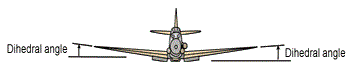
Dihedral Angle
Image: Dihedral Angle

Dihedral Angle

In the illustration above, A and B are two separate planes lying perpendicular to another plane C. The dihedral angle equals zero between planes A and B.

To demonstrate a dihedral angle greater than zero, first let aA and aB equal 90 degrees. Second, let plane B rotate around the line where plane B and C intersect while letting plane A remain perpendicular to C. For example, let aB (the angle where plane B intersects plane C) equal 60 degrees.

The dihedral angle (represented by the symbol J) between A and B now equals 30 degrees. This can also be viewed as the illustration below.

Dehidral Aircraft

Dihedral (Aircraft)

Dihedral angle is the upward angle from horizontal of the wings or tailplane of a fixed-wing aircraft. "Anhedral angle" is the name given to negative dihedral angle, that is, when there is a downward angle from horizontal of the wings or tailplane of a fixed-wing aircraft.

 Schematic of dihedral and anhedral angle of an aircraft wing.

Dihedral angle (or anhedral angle) has a strong influence on dihedral effect, which is named after it. Dihedral effect is the amount of roll moment produced per degree (or radian) of sideslip. Dihedral effect is a critical factor in the stability of an aircraft about the roll axis (the spiral mode). It is also pertinent to the nature of an aircraft's Dutch roll oscillation and to maneuverability about the roll axis.

 Measuring the dihedral angle.

Longitudinal dihedral is a comparatively obscure term related to the pitch axis of an airplane. It is the angle between the zero lift axis of the wing and horizontal tail. Longitudinal dihedral can influence the nature of controllability about the pitch axis and the nature of an aircraft's phugoid-mode oscillation.

When the term "dihedral" (of an aircraft) is used by itself it is usually intended to mean "dihedral angle". However, context may otherwise indicate that "dihedral effect" is the intended meaning.
Anhedral angle
Image: Anhedral angle

Source: Wiki

Posted on Friday, June 14, 2013 by Admin OG

No comments

Thursday, June 13, 2013


Differential Throw Ailerons
Ailerons that are set up to deflect more in the upward direction than downward are said to have Differential Throw. The purpose is to counteract Adverse Yaw.


Radio controlled aircraft with ailerons can benefit from differential throws of ailerons. Aileron differential means that the aileron that moves upward needs to be deflected by a larger angle, and the one that moves downward is being deflected by a smaller angle. This results in a more coordinated roll of the aircraft because if the aileron throws were the same, the equal angle of downward deflection causes more drag than lift for the upward moving wing, slowing the wing down and causing the aircraft to yaw in the direction opposite to the desired direction of turn (if any).
     While desirable, differential aileron throws is not really a critical flight function and is not implemented in many lower-cost computer radios. And, of course, it is not at all available in simple, non-computer radios. And if you sensibly choose to drive both ailerons with one servo then transmitter programming is of no use at all.
     There is a simple way of accomplishing differential aileron throws mechanically, by positioning control horns away from the hinge of the control surface. On this page we provide simple charts that allow one to measure and position aileron control horns to get precise maximum throw angles while achieving the desired differential.

To use the charts, first make a note of the deflection angle you need and of what percentage of the upward deflection angle you want the downward deflection angle to be (the differential). Next critical parameter is servo arm travel. This parameter is what you can change by placing the aileron linkage in the different holes in the servo arm.
 Next, follow the links in the table below to find the servo arm travel that will enable you to select the horn offset and clevis height, while giving the desired deflection angle and percentage of differential. Make sure that you use charts for the same servo arm travel.
Source: http://www.rcmix.com/diff_ailerons.html

Posted on Thursday, June 13, 2013 by Admin OG

No comments